
It has become a somewhat common practice to follow a “progression” of increasingly finer grit abrasives when sharpening a blade. In principle, this process is comparable to the procedure for metallographic polishing, which typically consists of three stages, coarse grinding, fine grinding and polishing. These steps are usually characterized by “the scratch pattern” for want of a better option. While techniques for metallographic polishing are very well established, there is inadequate understanding of precisely what scratches patterns are, and what is actually happening to the structure of steel at the micron scale. Additionally, as I have shown in the Optical vs Electron Microscope article, bevel scratches are not useful in characterizing the apex, and in general, scratches are not unambiguously characterized optically. To better understand the so-called “scratch pattern”, electron microscope examination and analysis is necessary.
In the SWARF! article, I showed that size of metal chips increases with grit size, although more slowly than might be expected. In the Abrasion Rate vs “Grit” article, I showed that rate of metal removal somewhat increases with abrasive size, with some exceptions. In this article, I will discuss abrasion and the role of abrasive grit size in the surface texture and sub-surface damage to the steel.
The interaction of a grit particle with a metal surface is called “single-grain grinding” and (from R.S, Hahn, 1962) is generally characterized by three modes; rubbing, ploughing, and chip formation. During hand sharpening, all three of these can occur, depending on the shape and orientation of the grit particle and the applied pressure.
A grit particle with a sharp corner or edge can penetrate the surface, and as it moves will shear the metal and expel a “chip” of metal. If a sharp edge isn’t exposed, or the local pressure isn’t sufficient for the grit to penetrate, rubbing will occur. In some definitions, burnishing is distinct from rubbing in that rubbing does not cause plastic deformation while burnishing does. For this discussion, I will include burnishing as part of the rubbing phase, as rubbing without plastic deformation rarely occurs. (To further complicate this picture, as I have shown in the What does Steeling Do? article, rubbing can also remove metal via adhesive wear).
Ploughing occurs when the grit particle penetrates the surface, but doesn’t expose an efficient cutting face; upheaval of metal occurs at the sides of the groove (just like the furrow formed by ploughing through soil). Although we are focused on the dimensions of the abrasive for now, it must be appreciated that the shape, orientation, density, friability as well as how firmly embedded the grit is in the sharpening media will affect the outcome. It should also be expected that chip formation requires a minimum depth of cut (or penetration) of the grit. For example, coarser grits with insufficient local pressure will not penetrate the surface and primarily rub or burnish the surface.
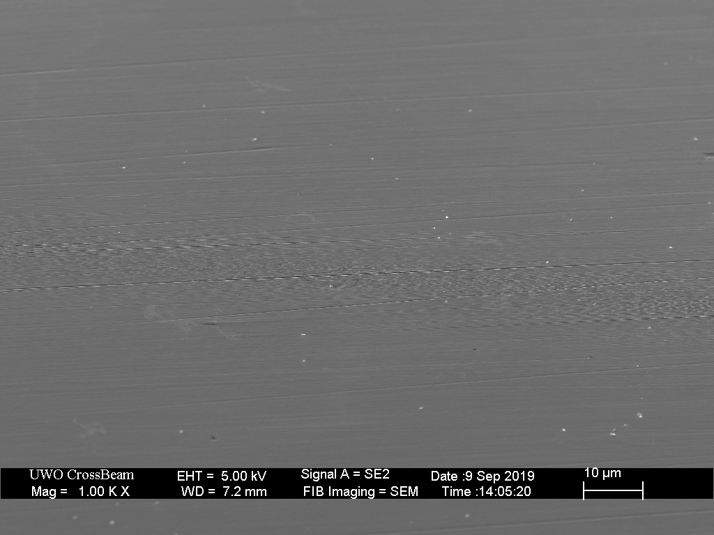
Initially, I will show polished surfaces with only a finite number of isolated scratches, or “single-grit interactions.” However, when grinding or sharpening, hundreds of single-grit events occur simultaneously, and rapidly overlap one another.
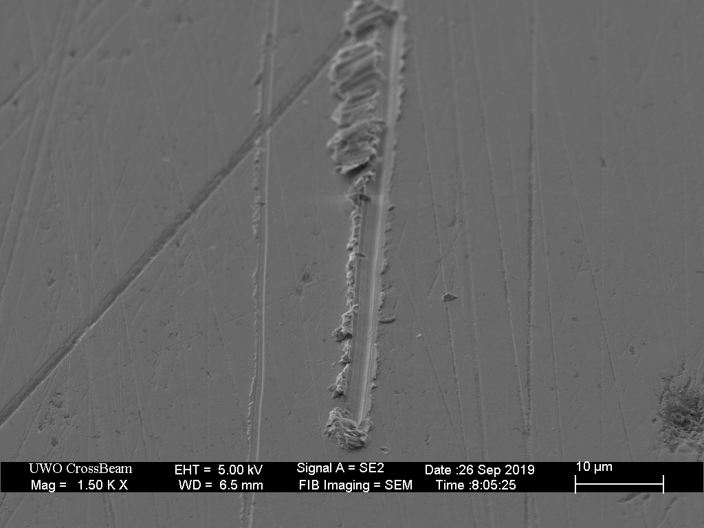
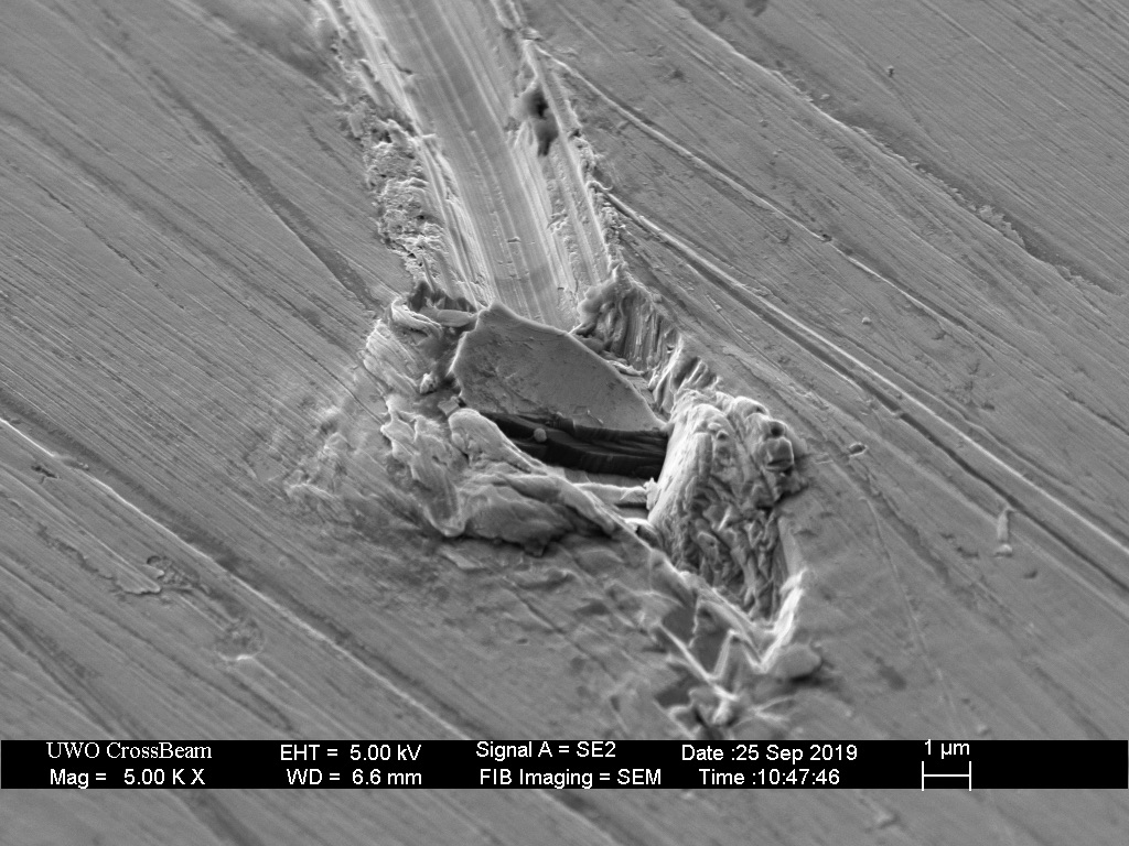
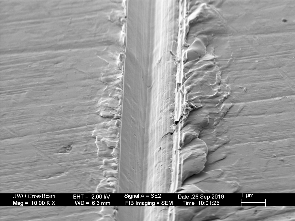
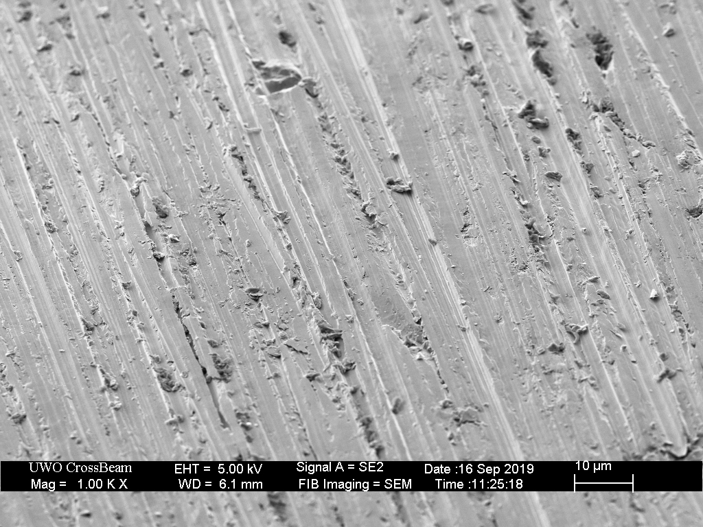
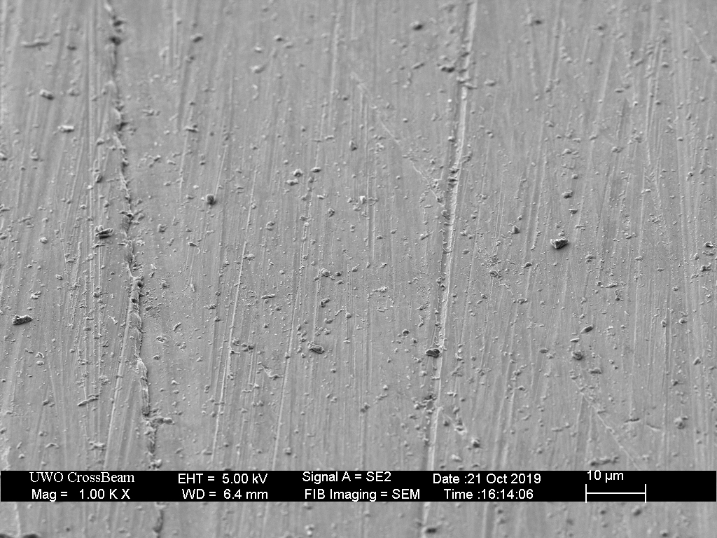
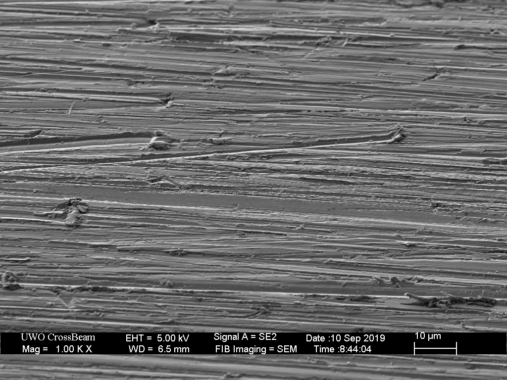
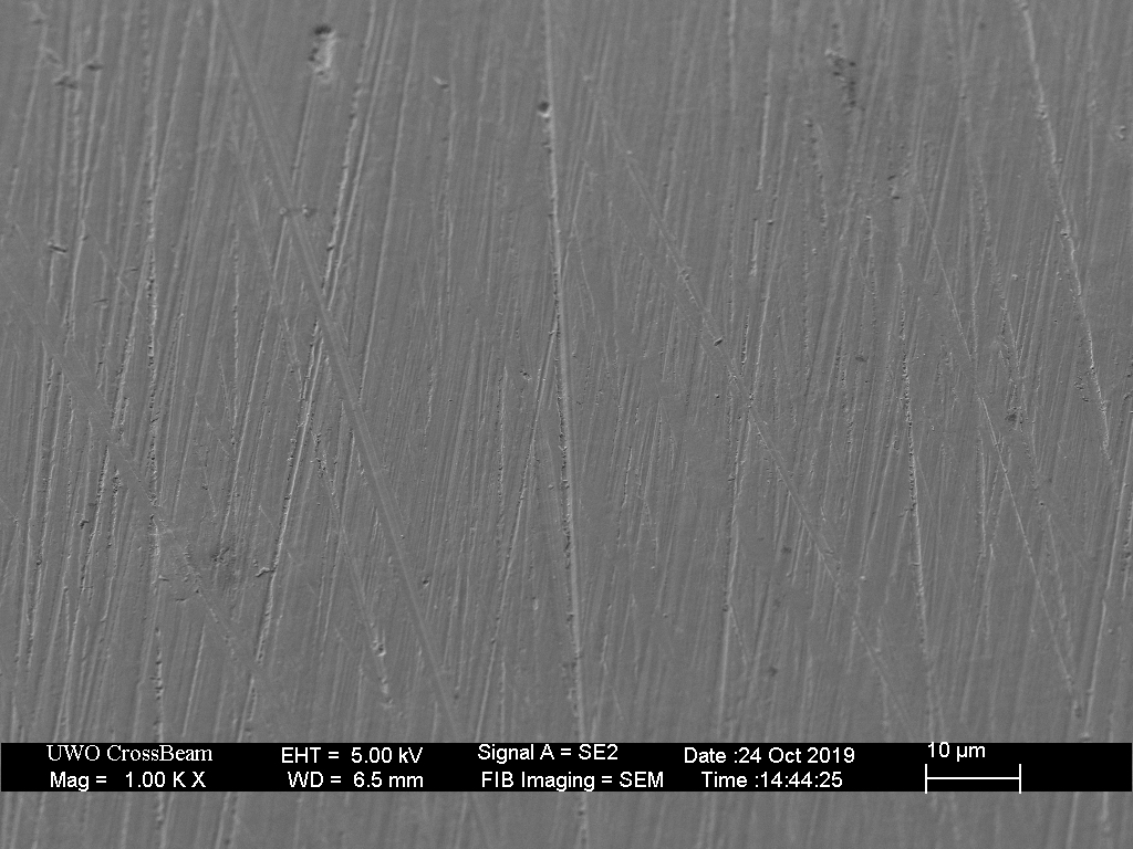
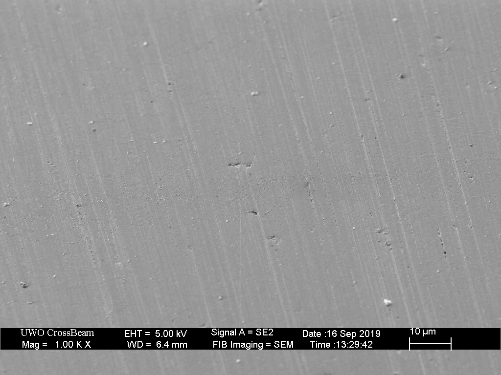
In the first set of images, a hardened carbon steel coupon was first polished, and then abraded slightly with 600 grit silicon carbide sandpaper (Norton Black Ice) to create a few isolated scratches on the surface. In the images below, we observe that both ploughing and chip removal can occur simultaneously.
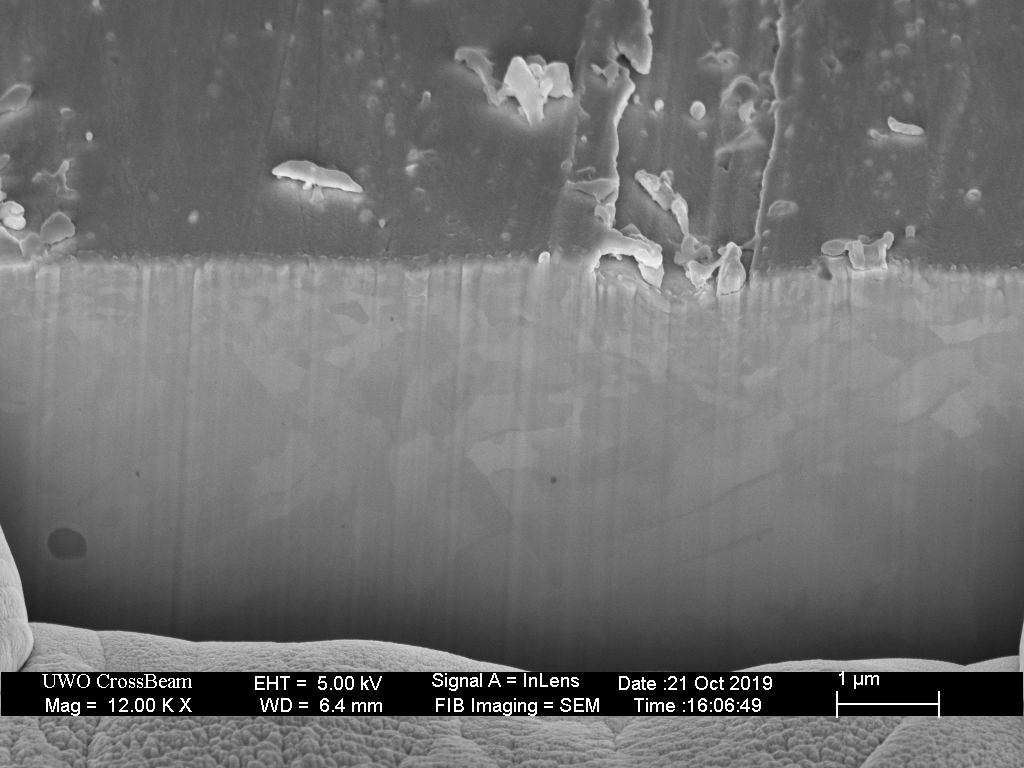
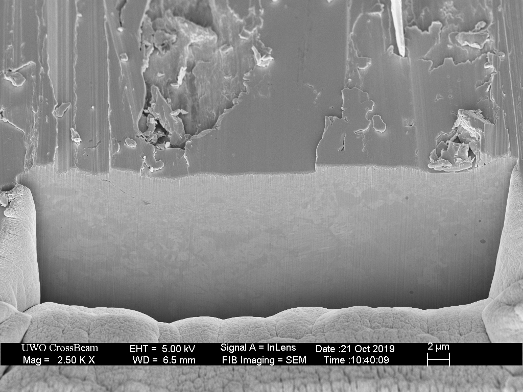
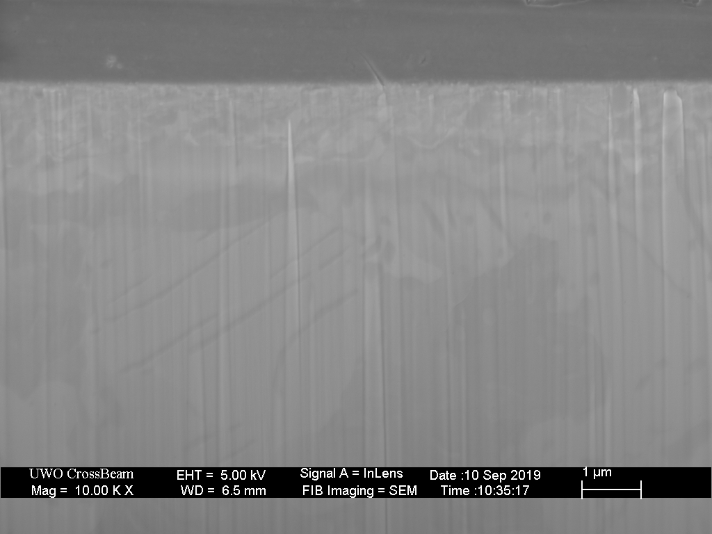
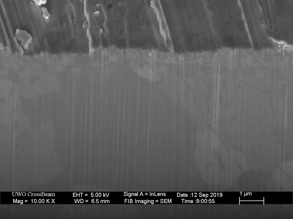
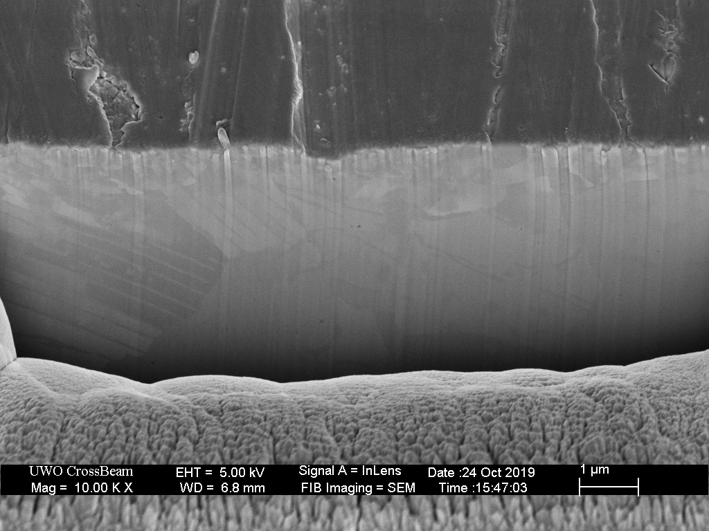
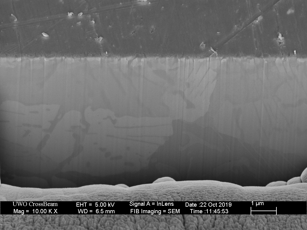
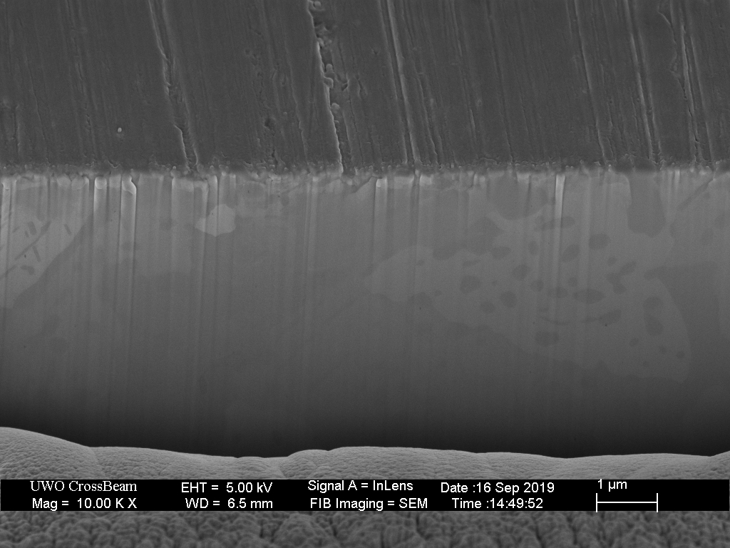
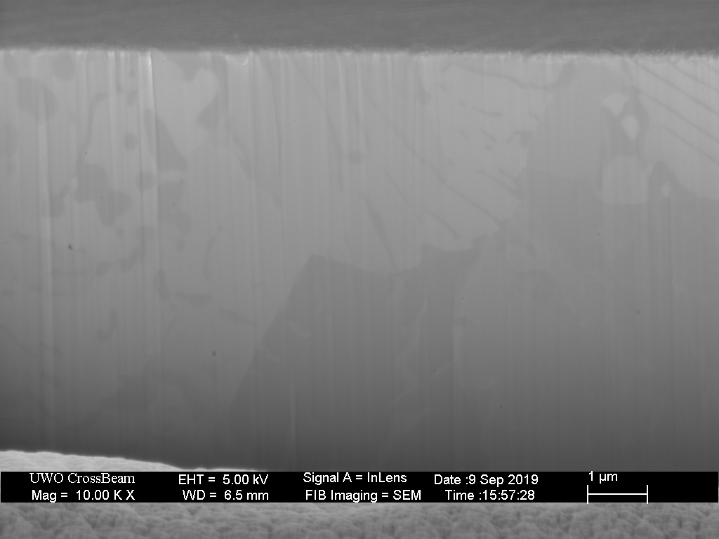
While the tilt-view images of the scratches are informative, a cross-section view is key to understanding this process. In the image below, the scratch was cross-sectioned after a thin layer of platinum was deposited on the surface to aid both the cross-sectioning procedure and the imaging of the cross-section. Not only is the topography of the scratch clearly visible, but the grain-structure produces contrast in the image. Unlike conventional metallographic etching, this type of grain structure imaging is subtle, but provides much higher resolution.
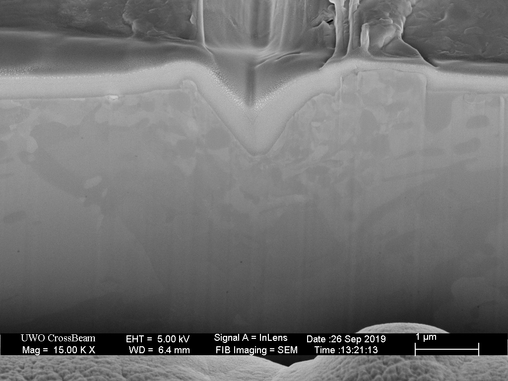
The cross section image is shown again below, with the line of the original surface marked in black. The region where the grain structure is disrupted/damaged is marked in red. The relatively large grains with underlying sub-structure are visible below the surface, but those grains are clearly distorted with sub-micron texture within about 1 micron of the scratch boundary.
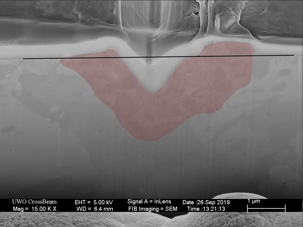
In the interaction of the single grit particle with the surface, there are three results;
- Metal is removed via the formation of a chip
- The surface is raised at the edge of the scratch
- The metal near and below the scratch is damaged.
When grinding, multiple scratches will form and overlap preceding scratches with each pass. It is observed that the surface reaches an equilibrium of texture (depth and width of scratches) with a characteristic depth/thickness of damaged metal.
This brochure: SiCpaper.pdf from Pace Technologies (metallographic.com) shows measured surface roughness on steel for a range of silicon carbide grit papers. Their data show that ANSI 600 (15.3 micron particle) was able to produce a roughness of 110nm (0.11 microns), less than 1% of the particle size. This polishing was done in random directions, and obviously abrading in a single direction as is typically done with sharpening will produce somewhat more roughness.
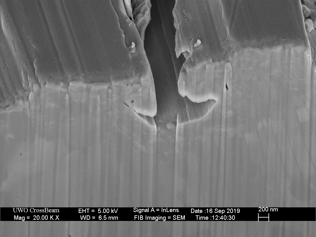
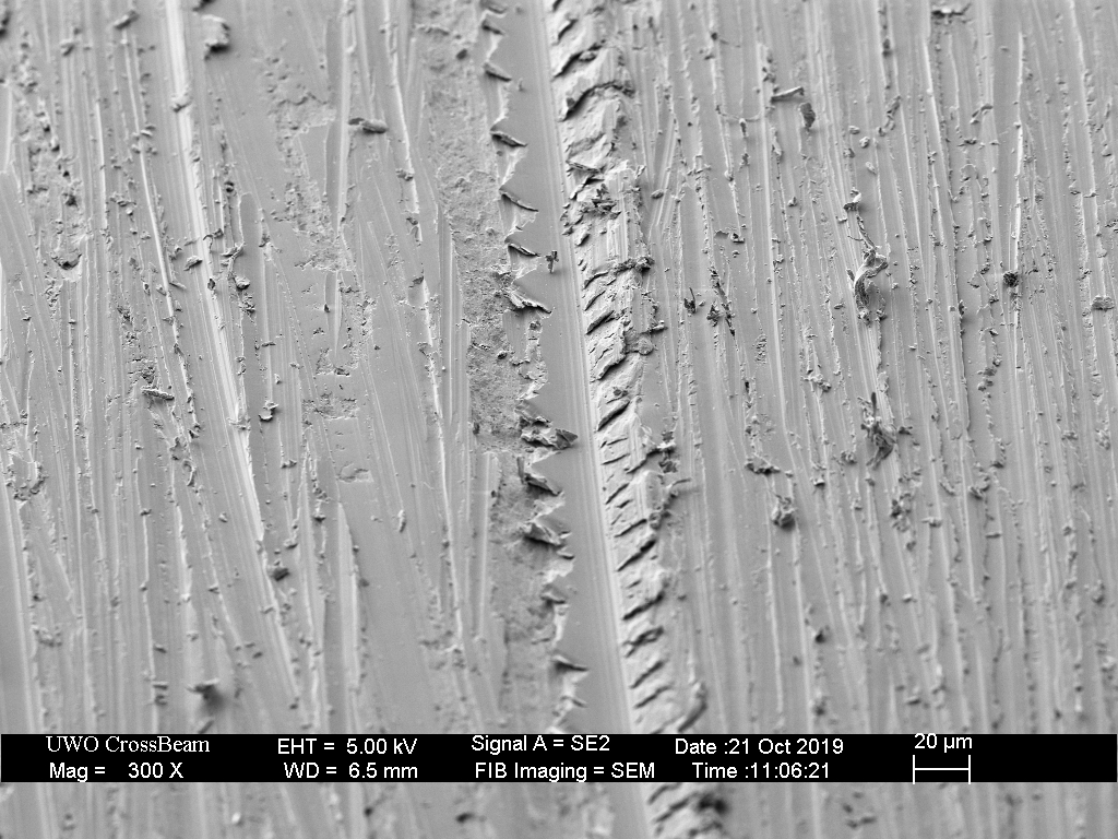
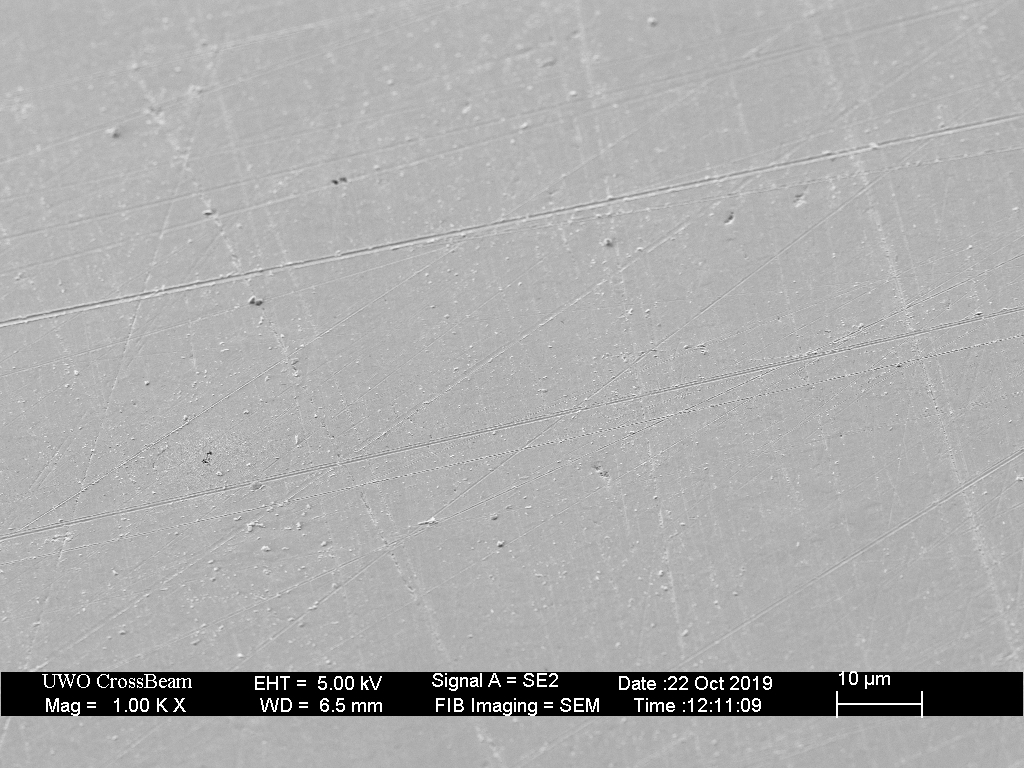
In the image below, we observe a scratch that has been partially filled in (burnished) by subsequent nearby grit interactions.
Rather than attempt to characterize the size and depth of “scratches” created by abrasive particles, which can be very misleading, I will examine the grain structure in the cross section to roughly measure the depth to which the grain structure is disrupted.
Observe that the Shapton Pro 320 grit surface is much smoother than that from the 320 grit sandpaper; however, the depth of damage is similar for both. This can be attributed to the fact that the stone is produces more burnishing than the sandpaper, resulting in a smoother surface.
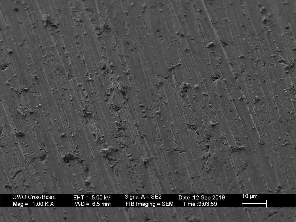
Comparison of the Shapton Glass 2k stone with the 2k sandpaper shows similar depth of damage, but a much smoother surface from the stone, again presumably due to more burnishing from the stone.
The goal of metallographic polishing is not simply to produces a flat surface with a mirror finish, but to expose the bulk crystal structure by removing the damaged layer that is unavoidably formed by grinding. As the images above have shown, this is achieved by progressing from coarser to finer grit abrasive.
With the Shapton Glass 2k (nominally 7.35 micron), in Abrasion Rate vs Grit, I measured an average removal rate of only 0.02 microns per pass across the stone. At the same time (and under the same conditions), we observe individual scratches that are up to 0.5 microns deep. These numbers suggest that most of the grit-steel interactions are simply rubbing and ploughing (and burnishing) with minimal metal removed. The surface finish, or “scratch pattern” is determined more by the character of burnishing that occurs than by the dimensions of fresh scratches.
Generally, we have observed that damage typically extends well below the depth of the surface roughness. We must expect that when sharpening with all but the finest polishing grit, the apex will therefore consist of damaged steel. The obvious question is what are the properties of this modified steel? In particular, is it less brittle and more likely to deform than chip?
The size of the grit particle is only one characteristic of sharpening media, the shape and orientation of the grit will determine whether an efficient cutting edge is applied to the steel surface. The more firmly attached the grit particle, the greater the shear force that can be applied and the deeper the cutting depth that can be produced. In Part 2 of this article, I will discuss mud/slurry/loose grit; when grit particles are not attached to the sharpening stone, they can roll between the blade and stone surfaces, in a “3-body” interaction.

18 responses to “Grit, Scratches and Sub-Surface Damage – Part 1”
I eagerly await part 2. It is interesting to ponder how the subsurface structure changes might affect the physical properties of the steel.
LikeLike
exelent new knowledge and model of grinding!
LikeLike
Fantastic post, like always!
LikeLike
As always, great work!! I always enjoy reading youre texts and looking at the SEM pictures
LikeLike
Read about this in an intro to basic metallurgy text… their assertion was that diamond abrasives are cold working, and should have less of an below surface effect… this seems not to be borne out by your images… typically the text said that the damaged extends as far as the size of the grit below the surface
LikeLike
There is a good amount of published research on grinding; however, the conditions studied don’t really overlap those we use in hand sharpening (coarser grit, higher pressure and speed). Particularly if you are grinding/machining soft steel, you don’t want to cold-work harden it. One big question is how hard is cold worked steel vs traditionally hardened blade steel.
LikeLike
Does temperature play a role in this grain disturbance besides the obvious plastic deformation? I had this question on Steeling, as there the pressure of a fine edge on steel with moderate speed reaches high levels and temperature just follows suit. I mean 30 laps heats a piece quite well and all that heat comes from a very thin interface.
LikeLike
Temperature really has no meaning in this situation. We use the concept of temperature to quantify the energy distribution. Thermally driven processes (like annealing and diffusion) rely on fluctuations of energy – if you imagine there is a statistical distribution, and only the very highest energy atoms can escape their position and move to a new one, and the higher the temperature, the more likely this can happen. See for example, Arrhenius behavior.
In these processes a large amount of energy is deposited into a very small volume over a very short time, and this is, by definition, a non-equilibrium process. We would like to imagine we could correlate what we know happens to steel at certain temperatures in equilibrium to some imaginary “effective temperature” in non-equilibrium, but that’s not productive in my opinion.
In reality, non-equilibrium processes can produce results that are not achievable by purely thermal(equilibrium) processes. Typically in the creation of meta-stable states.
LikeLike
I like to use heat and energy density interchangeably as I do not deal with sizes this small. I fully agree that the disturbance is the product of a meta-stable state induced by the energy input. For me the disturbed area bears similarity in shape and distribution to the heat affected zone found in welding and less so to the stressed area from a structural point of view. Also I find it odd that plastic deformation produces grain size change in the cold state. I mean cold forging, bending and rolling steel both exceed yield strength limits in plastic deformation but have little effect on grain size, other than some elongations. So just to kill my theories I would like to ask, was the polishing\grinding done wet or dry?
LikeLike
Welding occurs at a much larger length and time scales, where it is feasible to measure temperatures, and determine where melting occurs.
If you think about what happens when you force an indenter into the surface of the steel, you should understand that metal isn’t simply displaced to the perimeter like a liquid.
Just to be clear, what I am showing here is very well known, reaching back to the ideas proposed by Beilby a century ago.
LikeLike
Beilby led me to 3 articles and finally to Bowden and Hughes. They do infer melting from the inability of low melting point polishers to polish high melting point materials even though hardness might be lower in the polished material. Not trying to confirm my bias with a 1936 article nonetheless, I will concede the subject is orders of magnitude more complex than I previously thought. This is very interesting and thank you for a push in the right direction.
LikeLike
Informative and thought-provoking as usual. I wonder what happens when a “Super Steel” is substituted for Hardened Carbon Steel? Should we expect essentially the similar results with sufficiently hard abrasives used in these steps?
I too am looking forward to Part 2!
Thank you!
LikeLike
Wonderful stuff! Thank you!
LikeLike
Are you still planning the part 2 article mentioned at the end of this one?
LikeLike
I know what I wanted to say in a part 2, but I’m not sure this format of presenting my results makes sense anymore.
LikeLike
I wonder how much strain hardening you can do by using a coarse hone, then extremely fine hone to preserve as much as the dislocation rich sublayer as possible. Perhaps this would result in a stronger apex, and maybe even easier deburring due to a brittle burr? Thanks.
LikeLike
I don’t know the answer to this. Obviously soft steel can be work hardened, but can already hardened steel be made harder by work hardening?
LikeLike
[…] to larger impacts and produce greater deformation. This result is consistent with those shown in Grit, Scratches and Sub-Surface Damage. The length of the burr does not follow this trend. The longest burrs typically form at […]
LikeLike