

The purpose of this article is to briefly demonstrate the difference between optical and electron microscopy of a knife blade. The difference between “sharp” and “dull” will be measured in microns. The difference between somewhat sharp and very sharp will be measured in fractions of a micron. To directly “see” these difference with a microscope requires the ability to resolve features at those scales. The best optical microscopes can resolve down to a few tenths of a micron (hundreds of nanometers) while the best Scanning Electron Microscopes can resolve down to a few nanometers. While optical microscopes (and loupes) can provide a great deal of information about a blade, it is often indirect, and can be misinterpreted. The key to using optical magnification effectively is to understand what can and cannot be seen and correlate what we do see with other observations and our knowledge of what can and does happen to the blade during the sharpening process.
In a previous article it was demonstrated that side-view images are of limited value in assessing the apex geometry. Optical images are very difficult to obtain edge-on at any but the lowest magnifications. In this article, I compare only side-view images simply to demonstrate where optical microscopy falls short of electron microscopy in this application, and where it can be misleading.
When we examine an object in a microscope, there are two factors that determine what we can see – resolution and contrast.
Resolution is essentially how small of an object we can see or “resolve” – magnification is typically used to quantify resolution, although this number is often misleading.
Contrast is generally more difficult to achieve, and the microscopist will usually employ a variety of sample preparation techniques to control and/or maximize the contrast. The conditions of illumination and detection (and the design of the microscope) will significantly affect the contrast.
USB Microscope
The following series of images were taken from a single location on the bevel of a straight razor. The first image is from a USB microscope, although a high quality example, one designed for longer working distance and larger depth of field than for the highest possible magnification. The exposure was chosen to enhance the region near the apex, resulting in over-exposure further down the bevel. This may not represent the best possible image that can be achieved with this type of microscope, but it is typical.
When imaging a reflective metal surface, it is necessary to avoid the direct reflection of light from the source into the camera (like taking a flash picture of yourself in the mirror). This can be avoided by tilting the surface very slightly off normal; however, the light reflected and diffracted from the surface scratches will often dominate the image. The exposure was set in this image to maximize the information near the apex; however the remainder of the bevel is over-exposed as a result. In this image, it appears that the bevel is heavily and deeply scratched.

Optical Inspection Microscope
The following set of images were captured with a very high quality optical inspection microscope. There are other types of optical microscopes that can achieve somewhat higher resolution and that have other (possibly better) options for generating contrast. This particular microscope features relatively longer working distances (the object further from the objective lens) and larger depth of field (more of the bevel is in focus).
The image from the 10x objective has a comparable magnification to the image from the USB microscope; however, the features are far more clear and smaller features are resolved. In this image we see that only a small fraction of the surface is scratched, where the USB image gave the impression that the scratches were deeper and more abundant that the actually were. We also see that there is stropping residue on the blade.


At the highest magnification, the ability to resolve features at the apex is limited by diffraction. We can resolve spots/particles that are approximately 1/2 micron in size. Diffraction at the apex prevents us from resolving features below the 1 micron scale.

Scanning Electron Microscope (SEM)
The final set of images were again taken from the same area of the blade as the preceding images but with the SEM. As with optical microscopy, preparation and imaging conditions will determine what we can see (and those are optimized in these images).
The high resolution and absence of diffraction in these images allows us to see the small foil-burr at the apex, which was not visible with the optical microscope. These SEM images also provide a clear indication of the depth of the scratches on the bevel. By any estimation, the scratches are much shallower than suggested by the optical images.


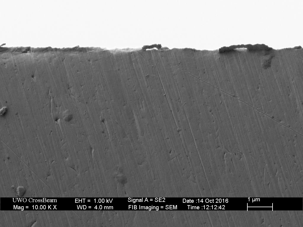
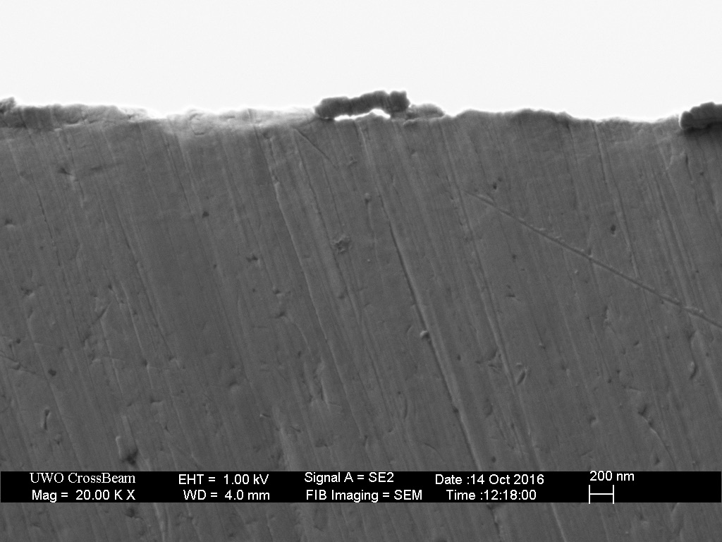
The small foil-type burr is clearly visible at the highest magnifications.

30 responses to “Optical vs Electron Microscope”
Great comparison Todd, really lets us see the difference!
LikeLike
As always, very enlightening! Thanks a lot. I’m always looking forward to your articles.
LikeLike
This reminds me of a thread I commented on a shave forum. The author called it “Encyclopedia of razor edge images”, and he took a side view image with a USB miocroscope after using various stones/hones in an effort to provide the reader with information about each stones/hones results.
I read it and replied “these look all the same to me”. He was upset that I’d stated the obvious. I was surprised to see pages upon pages of replies from other forum members saying “wow, great work” etc..when I know that they weren’t learning anything new. I also mentioned that repeating the same action and getting the same result but thinking it’s different is the definition of insane. I was then banned for 3 months for “calling another member insane”.
I hope that people who Google-search “razor images” or “magnified edge” end up here first rather than the above mentioned thread.
This website is all you ever need and I’m so glad I found it.
LikeLiked by 1 person
So you went to a straight razor honing forum and expected a rational discussion where constructive criticism is appreciated. You may want to re-evaluate who is the sane person there.
It is very difficult for most people to comprehend the relevant dimensions. Even as someone who has used Angstroms and nanometers on a daily basis for more than 25 years, I was astonished by how subtle the measured differences are between various DE razor blades. One of the reasons I show images over a range of magnifications is to try to convey just how small these feature are.
LikeLiked by 2 people
The same member swears by the DMT 8000. He in fact advocates it with fury. In another thread, I debate with him about why the 8000 should be thrown in the garbage.
After seeing his image thread, I then knew why he is hypnotized into thinking the 8000 DMT is great. Empathy ensued.
LikeLike
C’mon Todd, where is the entry on slurry honing I’ve been waiting for!? Still waiting to see how much the edges get convexed due to slurry honing, and whether some stones are worse than others. Haha, love reading your stuff man, it’s always interesting and informative. Keep up the great work!
LikeLiked by 1 person
You are probably the first to ever make this (and your other articles) visual comparison available to sharp edge makers. It takes access to the instruments, an interest in sharp edges, your skill in operating the microscopes and your generosity in sharing the information. Thank you.
I have tried various magnifying glasses, loupes and microscopes, but not an electron microscope. My favorite for looking at edges is a stereo microscope. Mine has high optical contrast and has 6x, 12x, 25x and 50x magnification options. I find that the 12x is the easiest to use, and very informative — particularly after seeing your high magnification SEM images. With your images in mind, the low power 12x gives a clue to what is on the bevel/edge. I use a bright light (quartz halogen machinists light) which shines from the side. I twist and turn the blade to reflect the light source. At 12x, I can easily detect a glinting foil burr from a 1k stone after edge trailing strokes. After an 8k stone, edge trailing stokes, the shiny edge is still visible. After a few strokes on the Mother’s polish strop, the edge “disappears” and the last few microns of the bevel go dark (no reflective scratches), even though the scratches on the bevel sparkle. This is a look I know from looking at Feather blades which appear to be sharpened with a roughly 4k stone and then polished on a strop which I now know is not a secondary bevel as might be seen from adding a layer of tape to a razor spine, changing the angle of the bevel near the edge.
I have recently bought a Coticule. At 12x, the scratch pattern on the bevel looks very different from that off a 10k Gokumyo synthetic stone. The Coticule bevel looks “misty” and the Gok makes a very regular and crisp scratch pattern.
Too sharp? I made a razor edge too sharp! The razor is worn and the edge angle too acute. I did not micro-convex the edge on your Mother’s polish denim strop. After stropping on a clean strop, the first two slices into the whiskers were very smooth, but the third already felt worse. A few laps on a clean strop allowed another slice or two. I returned to a 10k Gokumyo stone for a few laps, followed by the Mother’s denim strop, 0.25µm cBN strop and clean strop. This “dulled”, or micro convexed the edge enough to make it durable for a shave.
Magnifying glasses, loupes and USB microscopes were very not helpful for me. My stereo microscope is a great informer. It’s simple, but only after seeing the complexity of your SEM images. Looking at the results of sharpening explains feeling the results.
I, too, hope you will explain more about slurries. I have found that using an 8k slurry on a 10k stone is very helpful, thinning it out to finish, as used in a Coticule Dilucot method. I have also been experimenting with an Arkansas slurry, using a smaller piece of Arkansas to make the slurry.
LikeLike
Overall, I find the stereo-zoom microscope to be the most useful for evaluating sharpening progress, usually at the lowest zoom setting. The ability to tilt the blade under the objective to see how the light plays off the surface can tell you most of what you need to know.
LikeLike
I thought that this was wonderful. I don’t suppose you coulod give cost estimates for the microscopes you are comparing?
LikeLike
This particular USB is in the range of $1k, but I expect more affordable versions would perform just as well for this type of imaging. This one is most useful as an alternative to an SLR camera with a macro lens.
The optical microscope is in the range of $50k.
Each of the SEM images requires approximately 3 minutes and the research rate is $55/hr.
LikeLike
This stuff is BA!
Will you take images for pay? Are you saying you can do several images within an hour? If so, about how many? A YT video of you using this would be awesome.
LikeLike
These SEM images take about 60 seconds to collect. Including the time required to position the sample and make fine adjustments to the focus and contrast, it takes 2-3 minutes total per image.
LikeLike
I’d still love to see what edges look like on ice skating blades, with various sharpening techniques. I don’t suppose any of you could recommend a cheaper USB microscope that would be good enough? I have played with a very cheap nominally 100x USB microscope, but it really isn’t good enough to do the job. Or, if you are near Maryland, could we use yours?
Skate blades don’t need to be ultra-sharp – they are cutting into a fairly soft surface. Attempts have been made to use sharper edges, using narrow edge angles like those on knives. It doesn’t work – the edge sinks so deep into the ice that the blade stops gliding. Instead, people use edge angles of 90 degrees for speed skating, and a few degrees less for hockey and figure skating. I believe the classic technique also creates foil edges. Most hockey and figure sharpeners deliberately dull the edges after sharpening, removing or shortening the foil edges (I believe), to make the edges less fragile, and so there is less of a change in skating characteristics before and after sharpening. In addition, very sharp edges slow down the glide.
In fact, while I’m not certain, I think one mostly glides on the approximately planar surface at the bottom of the blade. On speed skates, the bottom surface is actually flat along one direction (no “hollow”), and is almost flat (e.g., about 16 – 21 foot convex radius) in the other direction (rocker). On hockey and figure blades, the bottom surface has a concave cross section (creating two edges, though one mostly skates using one edge at a time), with a radius of about 1/4″ to 1″ – most typically 7/16″ or 1/2″, and use somewhat shorter radius complex rocker curvature profiles. So a large part of what one accomplishes by a good sharpening is to grind the bottom of the blade (flat cross section for speed skates, hollow ground for hockey and figure skates) smooth, and also to leave the sides of the blade unscratched and smooth.
The edges are to create interfaces with the ice against which to push, and/or to constrain the blade to glide approximately along the length.
A couple first class skate sharpeners have told me that you only need to remove about 0.003 inches of steel (using power tools) for figure skating blades to make them sharp. (Hockey blades take more punishment, so you have to remove more. I’m not sure about speed.) Using hand tools, which I believe reshape the steel, I can do it removing less. One can re-straighten and re-polish the edge (if that is what I am really doing, contrary to what your experiments using cutlery steels show) and remove even less.
So at a guess, I think I need about .0001″ resolution or better to see most of what needs to be seen. Do you know of a good example of something fairly cheap that would do that?
Alternately, are any of you with good quality optical microscopes near Maryland, USA? I could bring you blades to look at, and work on them using a variety of techniques using hand tools there. I realize you are unlikely to buy them yourself – the best figure skating blades retail at about $800 / pair, and are easily ruined by one bad sharpening. The best Hockey blades retail at close to $100/pair, but I probably don’t know enough to sharpen them well. Plus, for either, there is a lot of learning, to do sharpening right, and in the end, they are perhaps best tested by use. If you don’t skate, that part would be hard.
Incidentally, have any of you played with re-focussing (de-blurring) image proccessng techniques to improve optical resolution or increase depth of field?
LikeLike
Optical microscopy can be very misleading if you don’t know what you are “seeing” or at least know what is possible. Once you establish what is happening with SEM, often the optical microscope is sufficient to distinguish between the various possibilities.
I don’t know much about skate sharpening, except that when I was about 10 years old I slashed my wrist on my freshly sharpened skate. It was an surgical-like incision requiring two stitches to close.
I do this sort of analysis professionally, and I expect it could be sorted out with a couple of 4″ lengths of blade and a few hundred dollars worth of SEM time.
Image stacking is only useful in limited situations. It generally requires a feature/line that is visible through the entire stack. For blades it works with straight and relatively large scratches.
LikeLike
Hockey skate blades basically bite on the corners just like figure skate blades. Both use the lubricity of liquid water to glide on the ice. The high local pressure melts the ice directly under the blade and basically creates the lubricant (water) as it slides. I have sharpened my own skates for decades.
It’s no different than sharpening any other edge, except that it’s radiused in between the edges (for hockey blades anyway). A sharp, well polished edge with no burr has always worked well for me. The trickiest bit is getting that radius centered perfectly on the blades so that left turns bite the same as right turns.
LikeLike
Thank You for tese last updates, hyper interesting as usual!!!
It is worth noticing that those very foil burrs could be spotted by the diffraction pattern with the optical equipment, and then confirmed with the SEM imaging!!
LikeLike
Yes, that’s one of the reasons I chose this particular blade edge for demonstration. The foil edge has some extra material beyond the nominal line of the apex, as well as some regions that are bent off center. Both of those cause some variation in the diffraction pattern. It will be more challenging to see this if there is debris or oil at the apex.
LikeLike
Oops – for those of you who don’t think in inches – The .0001″ resolution I seek is about 2.5 microns.
The bottom surface, ground by very expert sharpeners using polishing fluids, is mirror smooth – but not even as good quality a mirror as you see in dollar stores. If I assume that is flat to .5 to 1 wavelength of green light, that is about .5 microns – but no cheap optical microscope operating in the visible light domain is going to give me that, so seeing imperfect smoothness is a lost cause for me. Besides, the ice is a lubricated surface, and I don’t know how smooth the blade needs to be.
LikeLike
I wonder if we would still notice the foil burr from the diffraction pattern in a different case, if the foil burr would be not fragmented but continuos all edge long.
I bet it is more easy to catch discontinuity, amplifyied by the diffraction interferences
LikeLike
Foil burrs are usually misaligned, for example bent away from the last side that last touched the strop. It’s also quite rare that they are uniform in size along the length of the blade. I would expect they are often mistaken for micro-chips.
We can always get more information by watching as we change the focus, or by tilting the blade.
LikeLike
i have a very old Leitz-Wetzlar model: ( http://www.terapeak.com/worth/vintage-ernst-leitz-wetzlar-optical-microscope-medical-lab-equipment-w-case-yqz/291781093157/ )
and i use it, getting help from a led light i set up from the side 🙂
I love microscopy, and this blog of yours!!!
LikeLike
>I do this sort of analysis professionally, and I expect it could be sorted out with a
>couple of 4″ lengths of blade and a few hundred dollars worth of SEM time.
Aw, shucks. I hoped you were doing it for fun, or were a grad student who was making it a thesis project.
Unfortunately, I am doing it for fun, as well as to save money by not paying a professional sharpener and by removing less steel than most pros. A few hundred dollars is overkill.
The problem is there are a lot of variables in sharpening technique. So a few hours of SEM time isn’t really enough to determine the best techniques. And the final determinant is how the blade skates, not how it looks under a microscope. I’d like to create a video on hand sharpening. My feeling is that I can’t just say “Practice, experiment, test, practice, experiment, test…” I want to cut the learning time using the “magic of measurement”. A micrometer or high end calipers can help. But I think a reasonably priced optical microscope can help people determine if they are shaping the blade right too.
BTW, of course you can cut yourself on ice skate blades. One person told me she cut herself by bouncing the skates around on her leg or hip. And if you run your finger along the blade instead of across it, and use too much pressure, you can cut yourself. But you can learn not to do those things. In pro shops, blades they are mostly shaped using a grinding wheel – and then a flat stone is usually used to reduce the sharpness. With or without the flat stone, my guess is that doesn’t create as sharp an edge as multiple stones, a strop, and diamond slurries that hard core razor sharpening people like yourself use. But maybe it is easier to cut soft skin than to cut hair. I still have trouble shaving without cutting myself.
The one party that might have the money to pay someone like you would be BladeMaster. They sell a fair number of $10,000 – $30,000 sharpening machines. Maybe they could use your beautiful pictures to sell their product, as well as their instructional videos. (Those expensive powered machines aren’t actually better than purpose-built hand tools – maybe not as good – but they are much more impressive to the end-customer, who above all must be convinced they can’t do it themselves, and they are also at least several times faster than hand tools. In a pro-shop, time is money – I think most of the income comes from sharpening.)
What I mostly hope to get out of microscopy is to find out what the flat stone does. I think it straightens and polishes the edge. But your website has me wondering about that. You said earlier that straightening an edge, which feels like it is initially bent over by about 90 degrees, should break it (good figure skating blades have a rockwell edge hardness of about 60 – unless sharpening tempers the presumed foil edge). I think an optical microscope might be good enough to determine that, if I assume the initial foil is .001″ (25 microns) or so long. But the cheap USB microscope I bought a number of years back couldn’t resolve it well enough.
>Image stacking is only useful in limited situations…
That wasn’t quite what I meant by refocussing. In some types of imagery (e.g., some types of radio astronomy, occasionally high end optical astronomy [I think; especially to remove atmospheric distortion and scattering], Synthetic Aperture Radar [I worked a bit in that field], and MRIs), you compensate for poor focus, or for optics diffraction, etc., by figuring out the point-spread-function, and inverting it. (You use the convolution theorem, and work in fourier space. Specifically, the fourier transform of the inverse convolution is the reciprocal of the fourier transform of the point spread function.) What this means is that optics are NOT diffraction limited – the method is only limited by noise and compute time, if you are willing to do fancy image processing.
BTW, inverse convolutions are easy to do; the hard part is figuring out the point spread function whose inversion optimally solves the problem of sharpening the image.
In a crude sense, Adobe Photoshop deblurring does what is needed, but I doubt it is very sophisticated. It is a lot easier if the illumination is coherent and your sensor retains phase info – which most optical sensors don’t. However, to increase depth of field, you need to assume a different point spread function for different places in the image corresponding to different distances from the sensor. I don’t know if Adobe Photoshop can do that.
I suppose you could look at image stacking, if I understand it correctly, as a simpler form of the same thing, based on the assumption that the only parameter you need to vary is focal length. But if you are also compensating for diffraction and perhaps random scattering, you need something more sophisticated. I would also argue that with a sophisticated enough program, you don’t need to have something like a scratch viewable throughout all the images – though presumably that improves and simplifies alignment.
P.S. I’ve asked a couple people if refocussing was done in electron microscopy. Two people said no. If they are right, why not? Is there too much noise?
Do I understand this right: electron microscopes are limited in resolution by the difficulty of creating good lenses for electron beams, and perhaps diffraction around the target. I.E., all you can do is introduce electric charges and electric currents in and around the beam- e.g., charges grids, – and have a few wires carrying electric current to create a magnetic field – apparently not as controllable as shaping an optical lens or mirror. But I think that should still mean the output image has point spread functions that could be inverted.
Unless things are unpredictable, because something about the distortion is random, which would introduce noise.
LikeLike
One of the things I tell the students in my introduction to SEM course is that microscopy is all about resolution and contrast, and it’s quite rare that we run up against the resolution limit of the instrument when imaging real samples. The challenge with all types of microscopy is to generate contrast – this is accomplished through both sample preparation and the choice of imaging techniques and conditions.
Image processing is used with electron micrographs, but almost always for contrast enhancement or correction. For example, I use Image Pro http://www.mediacy.com/imagepro for contrast thresholding and statistical measurement.
I don’t want to discourage anyone from using magnification; however, optical microscopy will only give you indirect information about what is happening at the scale that matters.
LikeLike
>Hockey skate blades basically bite on the corners just like figure skate blades.
>Both use the lubricity of liquid water to glide on the ice. The high local pressure
>melts the ice directly under the blade and basically creates the lubricant (water)
>as it slides. I have sharpened my own skates for decades.
Current theory is that pressure induced melting doesn’t shift the melting point enough to be significant at ice skate pressure levels.
Instead, it is now treated as a boundary layer problem – i.e., at the temperatures that ice is slippery, the top few layers of water molecule next to the air always act like a liquid, perhaps because they aren’t bond in all directions.
However, maybe you can still find introductory level physics texts that say what you say.
I’ve been sharpening my own skates for somewhat less than a couple decades. I’ve changed my mind a few times about how sharp I want them, due to varying ice surfaces and skating styles.
LikeLike
I’m told that there are very expensive (e.g., $30,000,000) optical microscopes that use a combination of signal processing techniques together with special illumination, far UV wavelengths, and perhaps other methods, to get sub-nm resolutions. They are used by semiconductor and nano-fabrication companies to find defects before more detailed analysis with even higher resolution SEM (and, for still higher resolution, TEM) microscopes.
However, I was obviously looking for something cheaper. Besides, the aforementioned optical microscopes have narrow field of views.
Oh well.
LikeLike
I think there is some confusion with your information source – they are likely referring to extreme UV optical lithography – that is for writing patterns, not for imaging.
LikeLike
No confusion. One of my sources used to be a salesman for the company that made the microscopes. I had a long discussion with him. One uses EMs at a semiconductor company. The latter said the extreme resolution optical microscopes resolve 1/10 wavelength resolution. (Which is a lot better than any of the Synthetic Aperture Radar I worked with, though I am out of date.)
(Though I understand sub-wavelength resolution is also possible in lithography.)
I don’t know the details of how super-resolution optical microscopes work, though there is an article at https://en.wikipedia.org/wiki/Super-resolution_microscopy. It sounds extremely complex (perhaps that somewhat justifies the $30M price?), and ithey might not allow you to observe all things – e.g., I don’t know if blade edges could be observed, or if they might need to be prepped in complex and time-consuming ways. Also, the data collection and signal processing are quite slow, something the salesman mentioned. He said that in the semiconductor industry, where time is money, people usually just look for defect signatures that can be found without performing the full resolution enhancement.
Finally, the semiconductor company employee said that optical microscopes are only the first step in finding and analyzing defects – in the end EMs show more, though light penetration can sometimes be useful.
BTW, I do get what you said about brightness and contrast often being the limit. I’ve written research grade image processing and display software, so I probably don’t need Image Pro. Unfortunately, source quantization and noise limit the extent to which contrast enhancement is useful. And with any synthetic aperture or other super-resolution technique, noise ultimately limits resolution enhancement. There is only so far you can go. I am surprised that 1/10 wavelength is possible.
I wanted something cheap I could suggest people buy to quickly see how well they have sharpened an edge. None of these expensive devices and elaborate techniques meet that need. Maybe touch (feeling the edge, and feeling for sideways burrs), unaided sight (looking for optical imperfections in reflections from the surface), and the feel on the ice, are the best ways to do that – and are widely used for the purpose – but that is hard to teach and explain.
LikeLike
You can browse here to see the commercially available microscopies –
https://www.zeiss.com/microscopy/int/home.html
“super resolution” is typically referring to fluorescence imaging where the specimen contrast is enhanced with fluorescent dyes. This is not relevant to semiconductor or skate analysis.
Although probably this is more what you are looking for:
https://zeiss-microscopy.uberflip.com/h/i/434835692-why-your-feet-slip-and-slide-on-ice/191397
LikeLike
[…] happening to the structure of steel at the micron scale. Additionally, as I have shown in the Optical vs Electron Microscope article, bevel scratches are not useful in characterizing the apex, and in general, scratches are […]
LikeLike
I’d love to have a SEM if someone wanted to sell me one cheap, but after playing around with USB microscopes for a while I happened upon a crazy-good Amazon sale on a AmScope ME300TZB-2L-8M Digital Episcopic and Diascopic Trinocular Metallurgical Microscope — on sale about 75% off! I modified the scale to accept knives, which I just hold on the scale with a couple bits of 3M mounting putty.
The advantage of this metallurgical microscope (from my point of view) is the reflective illumination provided through the objective, although the separate back-illumination is useful for seeing edge defects. I haven’t tried anything using polarization or filters.
I mainly use PLAN 10X Objective, 10X Widefield Eyepiece. And, to state the obvious, this is looking “side view” at bevels, roll-off on those bevels, side-view edge defects, etc. A rolled edge shows up as a bright line on the edge, etc. So one can figure out a lot of the defects in one’s sharpening, but of course nothing like a SEM.
LikeLike